12 Results

mqtt

Search
In my Arduino MQTT Examples, I kept things simple by only subscribing to a single topic. One of the strengths of MQTT is that a device can subscribe (or publish) to multiple topics. The broker will sort things out. Even though my first example only showed one, it is straight forward to get the Arduino PubSubClient library to subscribe to Multiple MQTT topics. The quick answer is that you need to look at the MQTT response to find out which topic sent the payload.

tl;dr version

If you’re looking for a quick answer, here’s the magic code we’ll add to the callback() function.

void callback(char* topic, byte* payload, unsigned int length) {
if (strcmp(topic,"pir1Status")==0)
  // whatever you want for this topic
}
Keep reading for a more detailed explanation of how to Subscribe to Multiple MQTT topics with Arduino’s PubSubClient. Obviously, this code will work on Arduino boards with a TCP/IP interface and, of course, the ESP8266 based boards.

MQTT is an easy way for Internet of Things (IoT) devices to communicate with each other. This light-weight protocol can be used with a simple 8-bit Arduino to a Raspberry Pi to a multi-core PC to Amazon Web Services. It is that versatile.

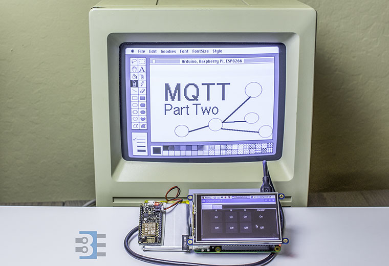
This MQTT Tutorial is broken into two parts. Part one is an MQTT Introduction. You’ll understand how publish/subscribe message brokering works. Next week, Part two will be a tutorial on using MQTT to communicate between a PC, Raspberry Pi, and ESP8266.

While the buzzword “IoT “is relatively new, there has been a long time “internet of things” in operation. Those devices are called the far less sexy term “M2M” or machine-to-machine. These devices, around since the 90s, contain a microprocessor, some sensors, sometimes electromechanical hardware, and a cellular radio. These M2M devices were (and still are!) the early “Internet of Things.” Thanks to Hologram.io, you can join this new/old trend for free.

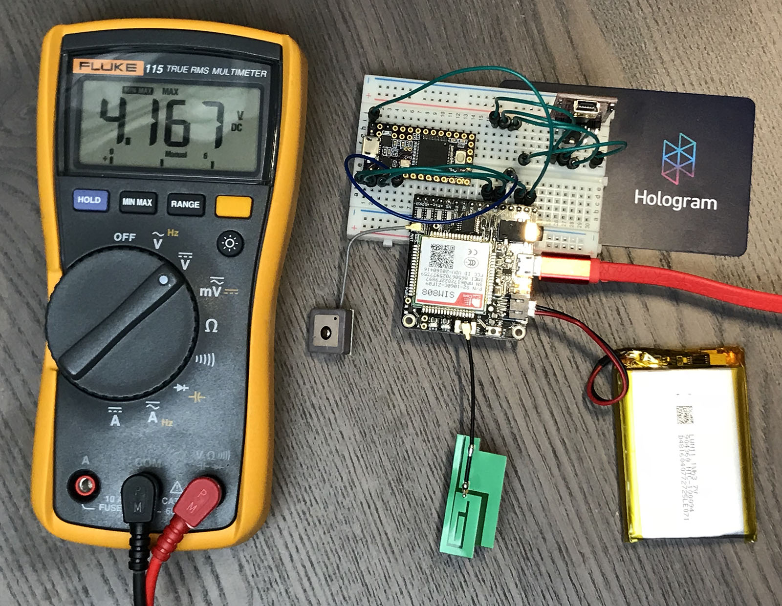
I decided it was time to up my IoT game with a GPRS, or 2G, data radio. In this post, I show the hardware I am using to create a 2G-based GPS tracker. It includes a Teensy 3.2 (Arduino) connected to a SIM808 Module (FONA) using a Hologram.io Developer SIM. It transmits GPS coordinates to an Adafruit.io Dashboard, which displays them on a map.

This post is not going to be a tidy tutorial. Instead, it is all the steps (and notes) I went through. I will cover:

  1. Hardware pieces I am using
  2. How to verify SIM808 (FONA) module is connected through Hologram via Serial Commands
  3. How to send HTTP/POST requests (including SSL) with the SIM808 (FONA)
  4. My (brute force) changes to the Adafruit FONA Library
  5. Code for sending MQTT payload (GPS Coords) to a dafruit.io dashboard

When done, you will be able to build something like a battery powered GPS Tracker, that updates over cellular. If you are in a rush, grab all the code from the FONA GPS Tracker Github Project.

As 2017 comes to a close, I looked back to see what readers made the most popular. It was an exciting year. The Arduino family came back together, Adafruit trolled the internet with rumors of a RadioShack buy out, and for me, I changed jobs.

Project wise I got my RetroPie SNES build completed, using an old Super Famicom case. This case is one I bought in Japan for 500 yen (about $5.) This work also led me to discuss voltage divider circuits. And I looked at a couple of scopes.

In case you missed it, here is what you as a reader found interesting over the past year.